CONTROLLING capacitance mechanically usually involves varying an effective, shared area between conductive plates. Some of these designs take the form of relatively small footprints with small 1

Voltage controlled capacitors are useful for many applications.
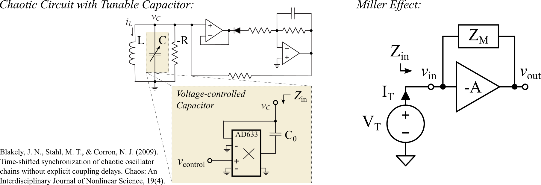
$$\begin{align} v_\text{out}&=-A v_\text{in} \end{align}$$
$$\begin{align} v_{ZM}&=I_T Z_M \end{align}$$
$$\begin{align} v_{ZM} &=v_\text{in}-v_\text{out} \newline &=v_\text{in}-(-A v_\text{in}) \newline &=v_\text{in}+A v_\text{in} \newline &=v_\text{in}(1+A) \newline &=V_T(1+A) \newline \end{align}$$
$$\begin{align} v_{ZM}=I_T Z_M &=V_T(1+A) \newline \end{align}$$
$$\begin{align} Z_\text{in}=\frac{V_T}{I_T}&=\frac{Z_M}{1+A}\newline \end{align}$$
$$\begin{align} Z_M&=\frac{1}{sC_M}\newline \end{align}$$
$$\begin{align} Z_\text{in}&=\frac{1}{sC_M(1+A)}\newline \end{align}$$
$$\begin{align} C_\text{Eff}&=C_M(1+A)\newline \end{align}$$
In the case of the tunable capacitor used by Blakely, et. al. 2, $A_v$ which has been applied as positive feedback. Note that the AD633 imposes a divide-by-10V mechanism as outlined in the AD633 datasheet. Positive feedback adjusts the previous Miller effect result to be
$$\begin{align} Z_\text{in}&=\frac{1}{sC_M(1-A)}\newline \end{align}$$
$$\begin{align} C_\text{Eff} &=C_M(1-A)\newline &=C_0(1-A_v)\newline &=C_0-C_0A_v\newline \end{align}$$
Importantly, the gain $A_v=+ \frac{1}{10} \cdot v_\text{control} [\frac{V}{V}]$ is a voltage-controlled gain that is implemented through the function of the AD633 multiplier.
$$\begin{align} C&=C_0-\Delta C \newline \end{align}$$
$$\begin{align} \Delta C&= \frac{C_0 v_\text{control}}{10 [V]} \newline \end{align}$$
Note that if $v_\text{control}$ exceeds 10V, the effective capacitor $C=C_\text{Eff}$ becomes unstable in this configuration (e.g. the effective capacitor assumes an impedance that is essentially negative in magnitude).
|
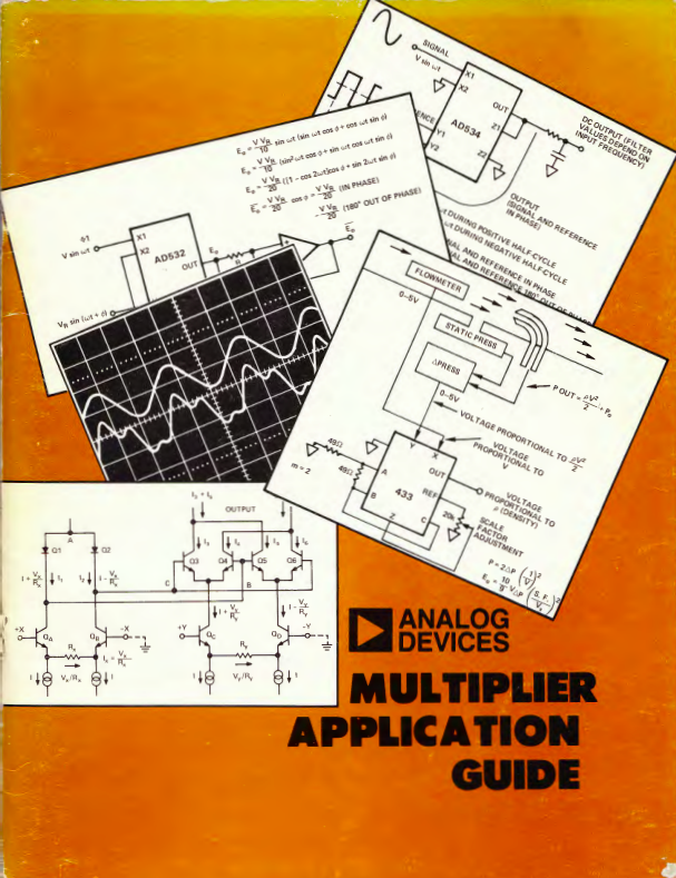
Many useful and interesting circiuts are provided in an application guide 3 edited by D.H. Sheingold and contains designs that were authored, tested and documented by notable electronic designers James (Jim) Williams and Barrie Gilbert. The voltage controlled capacitor application is not directly outlined in the 1978 edition of this application guide, however, the primary subsystem used by Blakely et. al. is the voltage-controlled amplifier (VCA) multiplier circuit described herein with the added trick of taking advantage of the Miller effect. |
-
Sizes of 1mm x 1mm to 25mm x 25mm appropriate for voltages below ~25V-10kV and frequences below 1MHz to 25MHz. Capacitances tuning ranges can be found from 0.2pF-1pF to 1400pF-3055pF. Examples include EW Electronics SGC3S100. ↩︎
-
Blakely, J. N., Stahl, M. T., & Corron, N. J. (2009). Time-shifted synchronization of chaotic oscillator chains without explicit coupling delays. Chaos: An Interdisciplinary Journal of Nonlinear Science, 19(4). ↩︎
-
Shingold, D. H. (1978). Multiplier Application Guide. Analog Devices. Norwood, Massachusetts. ↩︎